Organ Driver

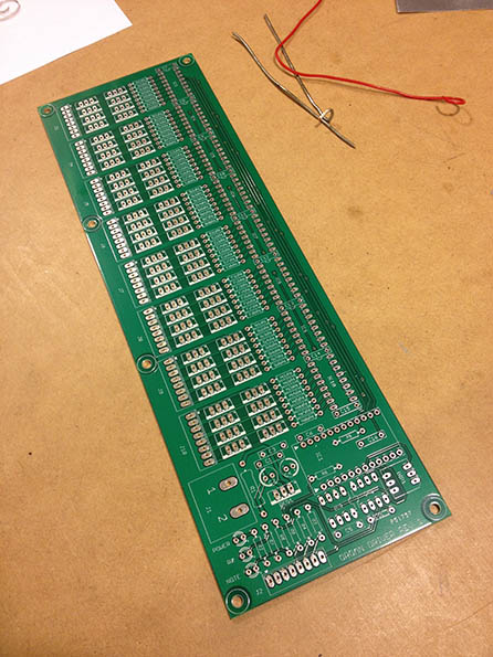
Valve driver board
Pipe organs are cool. I’m currently restoring one from Christchurch. It’s my version of a vintage car. This is a circuit board designed to handle the high current switching of the chest magnets. I did everything including electrical design, component selection, board layout, programming, testing, and installation.
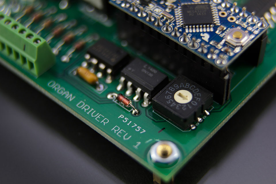
An Arduino was used to read midi signals and trigger the corresponding note. To differentiate between ranks, each board has a rotary dip switch to set the midi channel. There is also a fully buffered midi-thru so the boards can be daisy chained with no signal degradation.


Board layout was somewhat challenging as I was trying to minimize the footprint so I could cut cost as well as fit the board inside the chest. I used actual engineering equations to calculate the power dissipation of the traces so I could size them correctly. This is important as a single set of 61 magnets can draw well over 15 Amps at 15 vdc.
At first I thought cooling might be an issue, but the current rating of the main transistors is so far above what I’m using, they barely get above 30c.
While the whole restoration will be a very long process, I currently have the blower plumbed into the reservoir and the first chest. This allowed me to test the board under full wind load and actually play some notes. While it’s capable of passing 22 amp continuous, under actual playing conditions, it never got close to that. Some of the lowest pipes have double valves, so that will need to be tested in the future.