Wave
Folder

Modular Synthesis
I had long been interested in music synthesis since way back when I first got acquainted with pipe organs. This, combined with an interests in proceduralization and electronics, lead me to the classic modular Moog synthesizer. These are typically large electronic instruments made of smaller sound producing or processing elements such as oscillators and filters. They grew out of laboratory equipment and gradually became more and more specialize for making music. I eventually built up my own from modules purchased from synthesizers.com
There are two typical patterns for sound synthesis using these modular setups. One is to create a complex sound, and then remove elements until the desired tone is achieved. The other is to start with a simple sound, and add complexity until the tone is achieved. These two approaches are typically labeled "east coast" and "west coats" synthesis, respectively.
The modular I owned was of the east coast variety, so it had modules to simplify tones, but no modules to add complexity. This is where the wave folder comes in.
Synthesizer

Inside a single module

Adding complexity
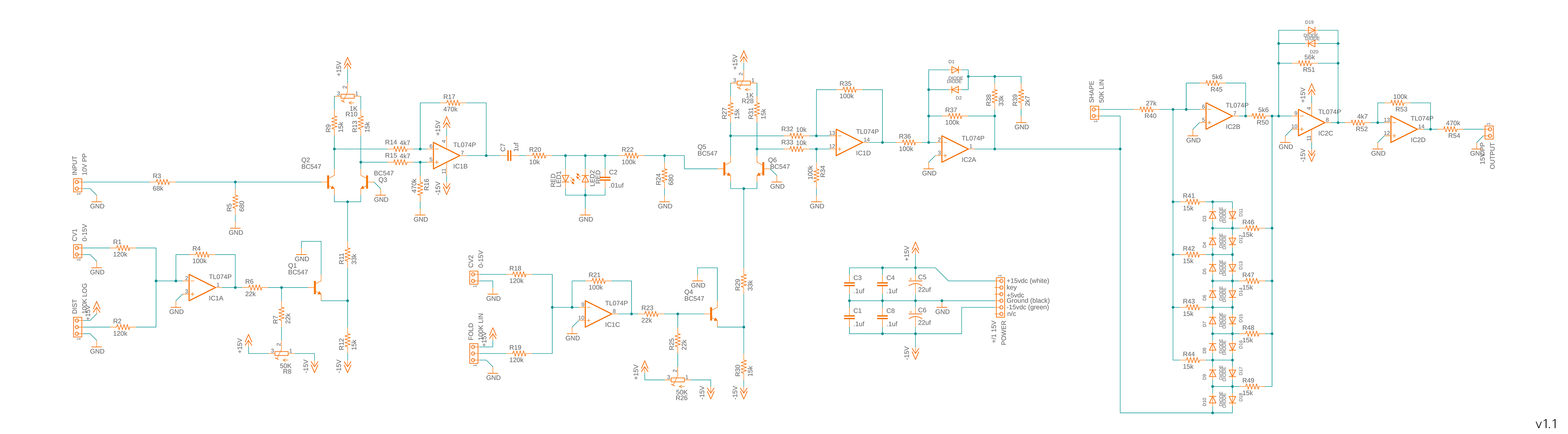
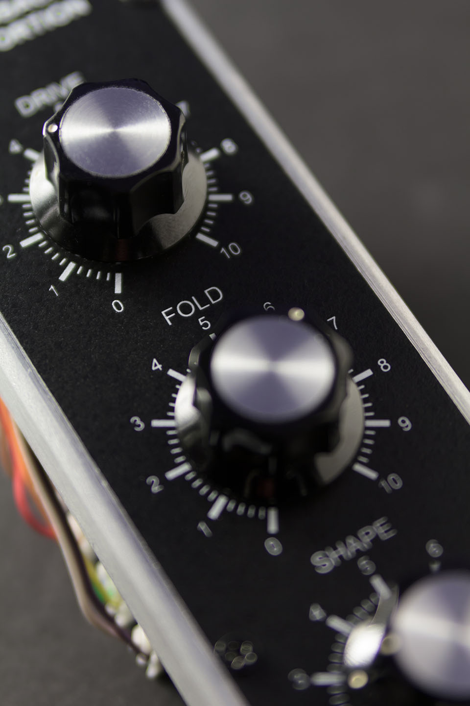
This module is designed to take simple tones and make them more complex. It does this through two methods: distortion, and wave folding.
Distortion
This is the process of essentially making the "corners" of the sound wave sharper, which in turn adds new harmonics (overtones) to the fundamental note. This is usually done by stretching the wave very tall (high amplitude) and then clipping the top and bottom off to make flat portions with sharp corners.
Wave folding
This also stretches the wave very tall, but instead of clipping it, the wave is reflected back down again when it reaches the maximum level. The more you stretch it, the more it reflects. Each new reflections adds new overtones and can even go so far as to remove the fundamental frequency.
The idea of combining these two methods into a single unit came from my study of the distortion module in Propellerhead Software's ReBirth synthesizer.
I am very happy with the results. This module serves as a great compliment to the rest of the synth and expands its tonal range significantly. Strings, guitars, and especially weird industrial music sounds are now possible with ease. Not quite "The Great Destroyer" level, but still fun.
Design
The distortion is based on an MXR distortion pedal using germanium diodes (LEDs) to create the hard-clipping effect. An op-amp drives the level higher and higher until the diodes shunt the excess current to ground.
The wave folder is based on a Jurgen Haible folder (B) with some voltage controlled amplifiers added by Yves Usson.
My contribution was adding a VCA to allow CV control over the distortion level, combining it with Usson's schematic, and building it all into a single module.
Prototyping
First, each effect was prototyped separately. Component values were modified to achieve the desired control ranges for the various parameters. The outputs were then compared to the original ReBirth distortion, changing just one parameter at a time. Some signal levels had to be adjusted when the two were chained together, but otherwise that process was quite simple.
The prototype was similar, but still quite some distance from what ReBirth had, however I liked it much better because most of the harshness was gone, and the tone sounded richer and more complex while not destroying the fundamental.
Distortion

Folding

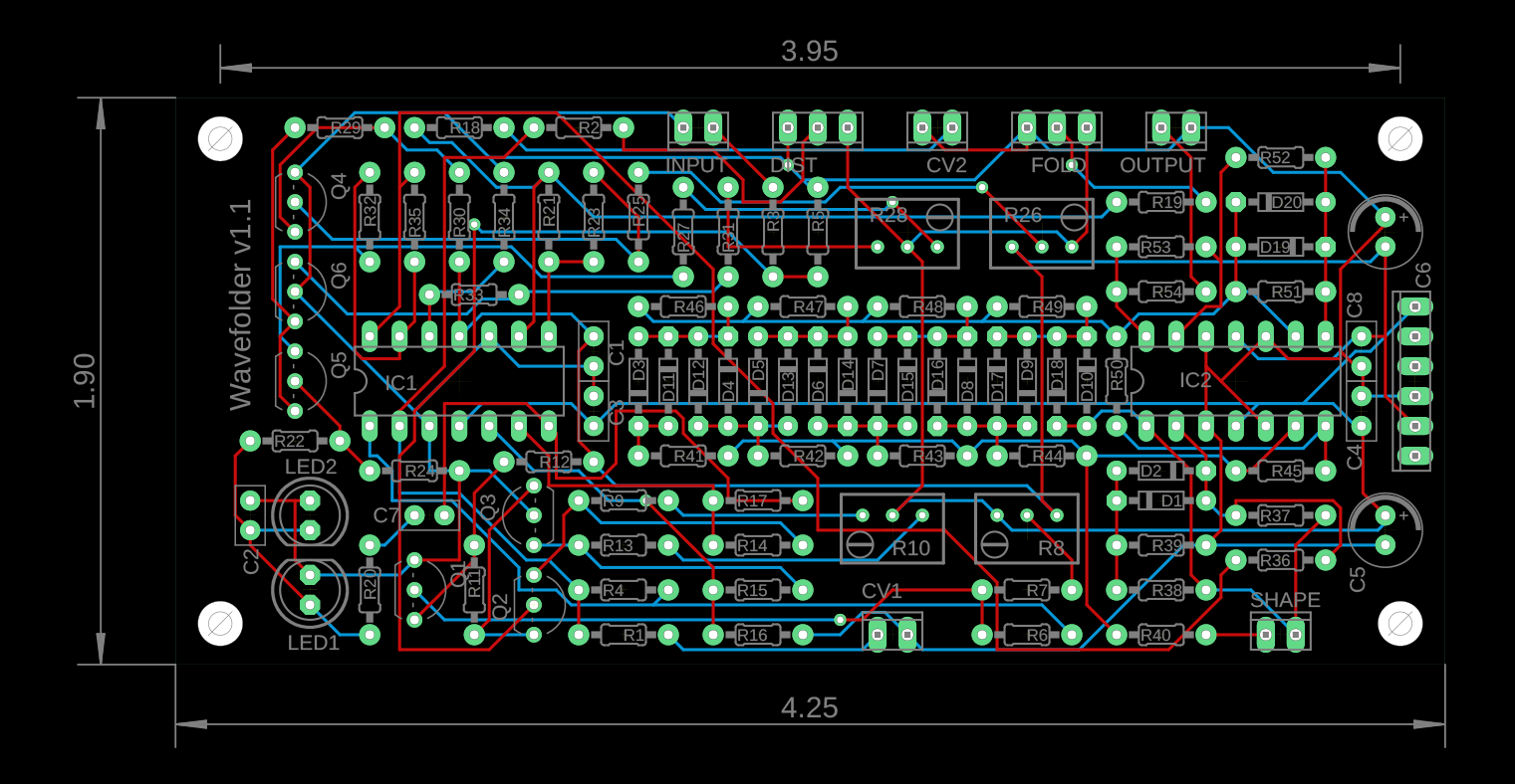
Boards were designed in Autodesk Fusion, and printed from jlcpcb.com.
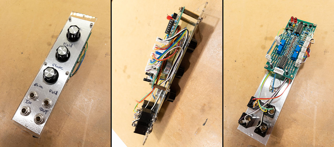
Electrical noise seemed to be an issue, especially for the shape parameter. I suspected this was due to a lack of shielding from outside sources, and poor grounding. To test this theory, a laser cut acrylic test panel was made, and aluminum tape was used to metalize the inside as a ground plane. When all the components were attached the noise disappeared.
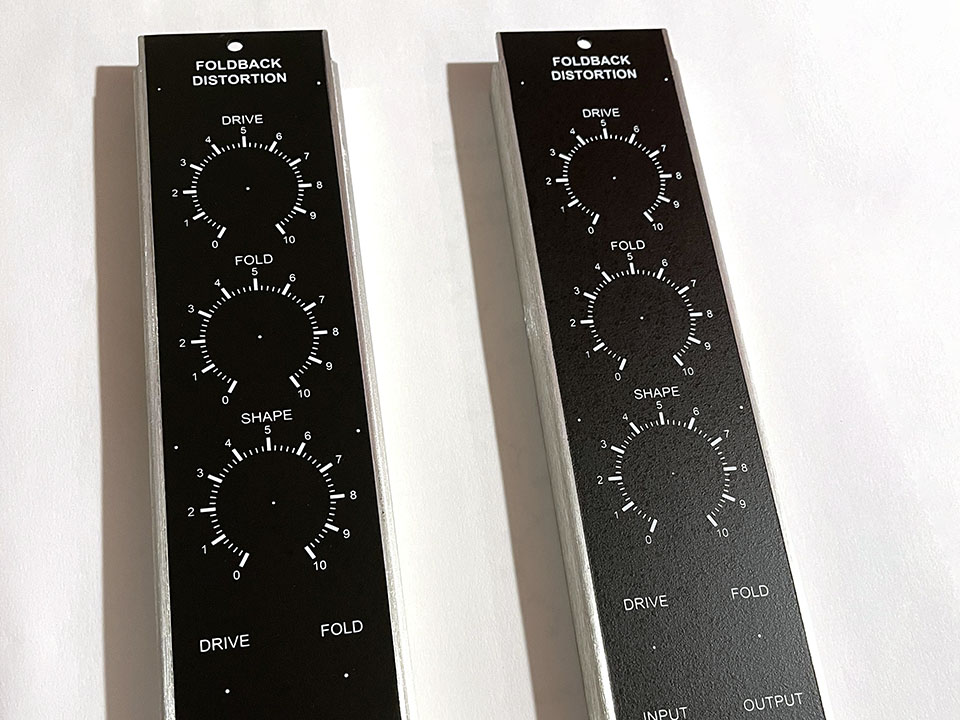
Front panel
In an effort to match the existing synthesizers.com panels, full silk screening was chosen. This was a new process for me and the first time I attempted it.
The panel blanks and knobs were purchased from synthesizers.com. The graphics were custom designed in Adobe Illustrator, however the free package inkscape would have been totally sufficient.
After a quick consultation, a 300 mesh count pre-exposed screen was ordered from westarsolutions.com. This resolution (300 mesh) was quite sufficient for the graphics and I would happily use this again.
Ink was Speedball acrylic white.
The panel was secured to a wood fixture using some blocks and hot-glue. The screen was mounted on butterfly hinge clamps such that there was about 0.06" of air-gap between the screen and the panel. The panel face was cleaned with alcohol. Ink was then applied using a syringe to an area of the screen above the graphic, and then squeegeed over it.
Fixturing the panel

Screen Alignment

Printing Complete
Holes Drilled

It took about three passes for the very first panel. Remember I had never done this before. The butterfly hinges made it very easy to lift the screen and check the print. The repeatability was well within 0.005" and multiple checks and squeegee passes were possible without loss of registration. I think thinning the ink slightly would have been appropriate for the 300 mesh resolution, and thus would require only a single pass. That said, the final print had a nice solid fill to all the elements and looked great. The second panel required only two passes and the process was much faster.
The panels were then allowed to dry for a few days before being drilled. To prevent metal chips from marring the surface, painters tape was applied over the graphics. No marks or ink-lift was observed, however next time I would drill first and screen second. The reason for doing it in the opposite order was that drill alignment marks were included in the silks screen graphic to ensure the holes registered perfectly. This turned out to be unnecessary since a visual alignment to the panel was possible through the screen.
Future improvements
This style of distortion worked very nicely, however there is a discontinuity in the drive parameter which I'd like to fix if I do this again.
The fold parameter works very well, but I would consider doubling the number of folds and possibly making the control exponential (or providing a linear/exp switch).
Shape made little difference to the sound and would possibly be more useful if left as a CV input only. Its main utility is giving LFO-PWM like sounds to any waveform, and is not very useful at static values.
There were also some errors in the board footprints which necessitated a v1.1. This was due to the project sitting shelved for over 10 years and then not thoroughly being checked before fab.
Using standard jobber drills on the front panel was efficient, but due to the extremely soft nature of the 5052 aluminum plate the bits did not produce as nice of a hole as I'd like. Next time I would consider milling. I would also silk screen after milling.
Ink durability would be a great thing to test, as well as different viscosities.
Lastly, more room could have been allotted for the connectors around the edge. I copied what Synthesizers.com did, but it turned out to be a little too tight for my liking.

The cookies were the most important part.
Thanks Mom.
