Volt Meter
Clock

Digital to Analog
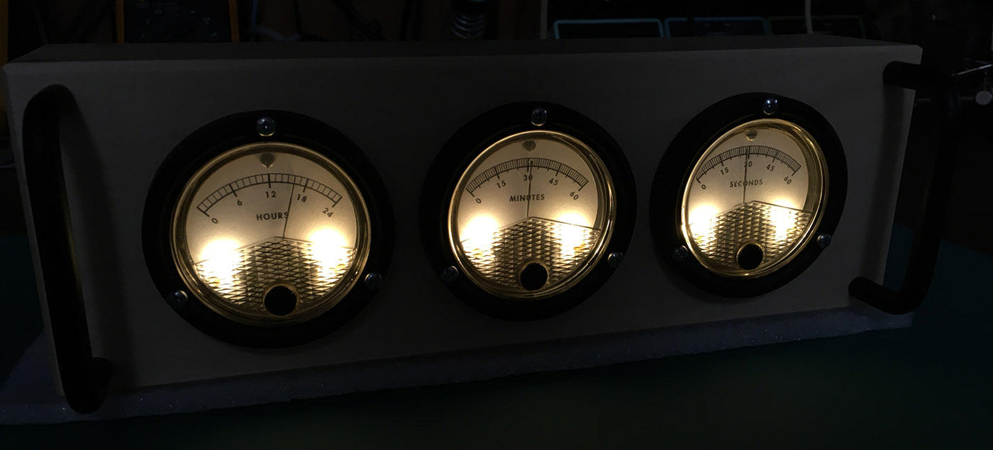
Built as a present for my Dad, who likes all things clock and electronics related. My younger brother had started to acquire parts and build a housing for this clock years ago, but he lacked the tools and time to finish it. I used his artistic design for the clock, and finished the technical design and manufacturing.
The clock is quite simple and you can find many like it on the internet. Inside, an Arduino gets the current time from a real-time clock module. This data is then used to PWM the outputs to the analog meters.
Design
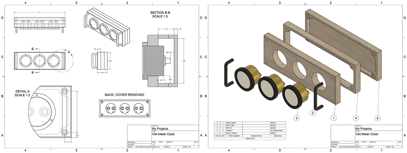
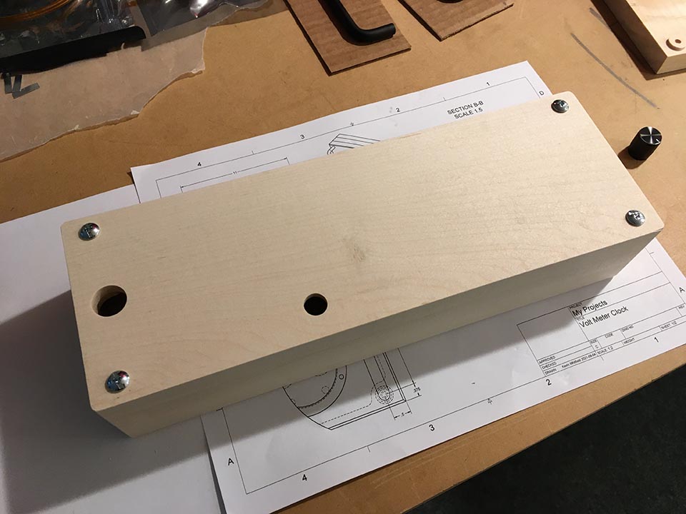
The housing was machined from 3/4 maple. The layers are held together by four screws which also attach the handles. Each meter is screwed to the front, and a custom board carries the electronics within. A single encoder on the back allows you to set the time and the back light brightness. Pressing it cycles through each meter.
Electronics
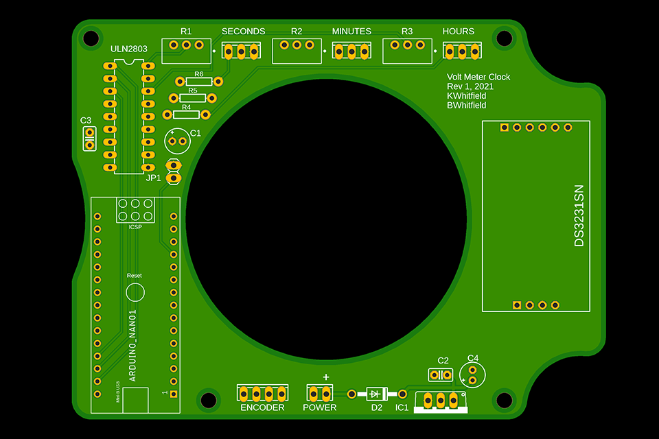
An Arduino nano is used to interface with a DS3231SN real-time clock module which carries its own memory and backup battery. The current drive for the meters is handled by a ULN2803. Meter gain is through three trimmer pots and offset is achieved by using the mechanical adjustment on the meter face. R4-R6 were left unpopulated until suitable backlights were found. After many tests some warm-white LEDs were chosen and the correct resistor used. Power was supplied by a 7v adapter and regulated down to 5v. JP1 is provided so the arduino can be re-programed without having the computer also power the rest of the clock.
faces
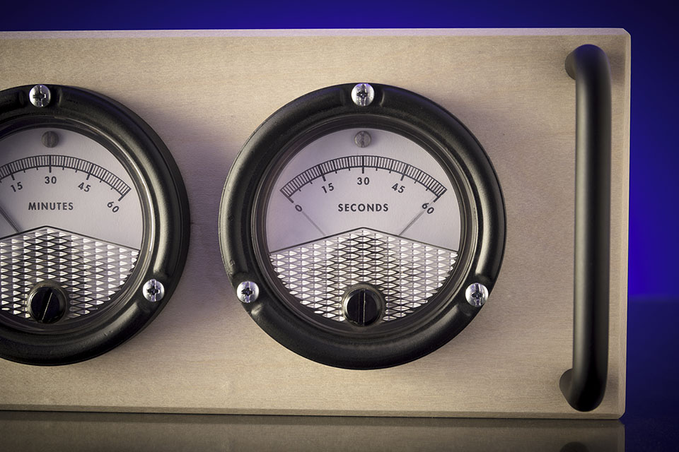
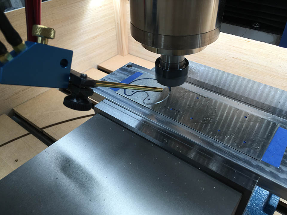
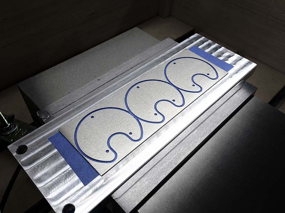
The original faces were removed and scanned into the computer. New ones were designed using the old as reference, and printed out. New face plates were milled out of 1/16 aluminum (to a totally unnecessary 0.0005" accuracy). The graphics were then glued onto the plates by hand using a lightbox for positioning. The face outlines were made slightly offset so they could me seen around the actual metal plate to aid in alignment.
Meters
The meters proved a bit difficult to work with. Not only were they old and somewhat damaged, but also had non-linear stiction problems from day one. Several attempts were made to use over-driven current pulses or low-frequency PWM to help overcome this, but ultimately a simple calibrated lookup table was used to get the needle in the right spot (most of the time). The seconds meter still exhibits some range issues on occasion, however it is the least important meter.
Code is available here: https://github.com/KevinW1/voltmeter_clock
Future improvements
Using better meters would have made this project a whole lot easier. Not only would backlighting be more straight forward, but higher-quality meters could minimized the nonlinearities. Making the USB port available on the bottom of the clock would have been nice as well. I had experimented with using incandescent lamps as well and think those would have been a better aesthetic fit for the design. They ended up being rejected due to power draw.
